Response to Art & the API + Google's Dev Art

Read Art and the API and look at some of the art projects that use APIs at Google's Dev Art. Write a blog post that discusses Thorpe's piece and/or one or more DevArt projects and/or other projects that make use of APIs

Coming from a still developing film career, I'm now searching for something more concrete with my new studies than to go through life begging for people with money to consider me and my creativity as legitimate solely in the context of art. So normally I resist it mentally when I hear ITP referred to as an art school.  But despite my twice-bitten mistrust of the term "art" I always come back to this kind of thinking, quoted in Jer Thorp's piece, which I do believe in: 


"The specific function of modern didactic art has been to show that art does not reside in material entities, but in relations between people and between people and the components of their environment." - Jack Burnham


Ideas - making ideas clear through creative association and implied analogies and whatever else is in the tool box. But it's analogy of form, concept, emotion, spatial relationship et cetera that gives artists - and now especially "digital" or "tech" oriented artists the free pass to step in and analyze any topic with factual data to find those connections and then show them to an audience.  An . Application Programming Interface is the common language that writes, ecrypts, and unlocks that hall pass. 

Starting at ITP marked the first time I'd really heard about APIs, open or not.   A commenter on the blog sums up the simple approach to this concept (which strikes me as a newcomer as well): 

 "I like the focus on the API over something static like a database. It empowers the artist to transform up-to-date and changing data into something equally up-to-date. Much more impacting, much more interesting".

P.S. Looking at the Dronestream twitter feed makes me lamely ask: "What the fuck is our country doing obliterating people with drones?"  Stirring up an anthill to feed the machine that makes money burning the ants with a magnifying glass. 

Again, the closing quote from Jack Burnham "The significant artist strives to reduce the technical and psychical distance between [their] artistic output and the productive means of society" rings with my vibes. 

P.P.S All of the direct API links seem to be broken in this write-up. 

First Document Object Model (DOM) with HTML & CSS

http://104.236.52.219:3000/week3/badlandsDOM.html

I was moderately delighted that I somehow subconsciously absorbed the concept of nesting functions.  I was trying to add a "refresh" function to get an ID and replace the secondary inner html with the original.  A clumsy workaround to an actual loop to reset something surely but I wanted to make it work anyhow.  It wasn't working the way I wanted because the document.getElementById function was skipping the secondary or replaced inner HTML and was instead grabbing the original defined earlier.  So I thought of nesting the "refresh" function and replaced the secondary inner HTML.  There is still a problem of course - I can't then go back forward through the replace function to go from the tertiary inner HTML to the secondary.  That's again evidence I need to implement a loop.  I also used my CSS code from my Week 1 homework and adapted that pretty lightly. 

An aside: So, this isn't a sparkling effort but I'm still working through how best to learn to use languages and how to breakdown leftover learning difficulties/avoidances from fifth grade math class, etc.  People keep saying all you need to do is spend time with it and it's completely true. It's the same with math. Hardly anyone is born good at math but I didn't know that back then. It's your attitude towards the work that has to be put into it.  

Foray into p5 with HTML

Initially had some syntax error which I got through by troubleshooting like this: 

Using the empty_example from the p5.js complete download I was able to transfer the Processing sketch line by line; testing periodically in my browser using the local server. 

I eliminated syntax errors and was able to get the p5.js version of my Processing sketch up and working.

However, my file structure or server connection still had an error so I was unable to actually open the index.html file with Google Chrome.  It kept returning a 404 error or this:

...despite being able to call up last week's HTML project. 

Here is a video documenting my p5 sketch.


M I N D M A P : project proposal


FullSizeRender (10).jpg


Mind Map is a dynamic quadrant continuum designed as a tool to connect minds at ITP or in any diverse, collaborative environment.

Users input areas of skill, interest, or project topics via a form or mouse click and can gauge proximity to clusters of other users. You can hover over each point to get user contact or project info. Ultimately I'd like to it be a point of first contact if users wish. 

At ITP one often chances upon classmates' interests haphazardly over the PBJ table or at the equipment room counter while looking for the same sensor.  Before coming to ITP my biggest unanswered question was: How to best tap the well of shared and divergent interests to find useful collaborations or share-points? 

On a basic level it is similar to the intuitively logical yet flexible New York Magazine Approval Matrix: 

And somewhat superficially may resemble Abe Rubenstein's Foosion ITP foosball scorekeeping site in form and spirit. 

Questions for ITP students/users:

WOULD YOU LIKE TO USE THIS TOOL? 

WOULD YOU LIKE TO USE A WEIGHTED SURVEY FORM TO CALCULATE GRAPH POINTS? 

or

WOULD YOU RATHER USE A MOUSE CLICK TO PLACE IT YOURSELF? 

DOES ADDING A CATEGORY SUGGESTION FIELD MAKE SENSE? 


Haptic Bike Navigation Project Update #2

Timeline for prototype completion: 

http://bit.ly/1sflFQi

Bill of Materials: 

http://bit.ly/10kJsXg

Our team (Sam Sadtler, Marc Abi-Samra, Catherine Rehwinkel) is currently designing the pseudocode and user interface aspects of our haptic bike navigation system.  We are currently considering creating a program which includes two basic navigation/routing options for the user: one provides the cyclist with the most economical route on destination input from the user and then uses a simple code of vibration feedback to signal the rider to turn.  The second, which we recently concieved of are referring to as 'True Destination' (time allowing paired in this iteration with a 'True North' functionality), gives the user a range of degree based on each turn decision the rider makes.  On destination input (a geolocation point, an address or simply a Cardinal direction) the rider can start the journey in any direction and receive a range-expressive signal which guides the rider to take a turn in the best direction.  This method differs from the first in that it doesn't prioritize route efficiency or any specific series of street turns because it prioritizes cyclist safety. The cyclist may turn when he/she feels safety is optimal and still arrive at the destination using a deliberate route. 

Below is a map which was generated using JavaScript and the Google Maps API. We are in the process of making a JavaScript web application which, in this scenario, will pull a user's GPS location and then produce a tone when it is time for them to turn. Ideally the tone will produce enough voltage to turn on a set of LEDs. If the headphone port does not provide enough power we will send the tones to an Arduino Mini which will have its own power supply be able to control the electronic components.

And here is a sketch of our "True Destination" safety routing option. 


We continue to refine our user survey strategy.  We have been talking to CitiBike users at stations to gather feedback and insight about design priorities.  One major insight has been that CitiBike users seem to be bikers with a routine or else are tourists or non-serious cyclists.  A pattern which has arisen is that casual cyclists do not seem to consider that there could be another option to the dangerously distracting audio-visual feedback from a smartphone naviation system.  We are adding bike shops to our user research because we have decided to prioritize safety and believe that serious recreational or professional cyclists may be our initial target user to design for. 

Post by Catherine Rehwinkel & Sam Sadtler

Computational Media Data Project

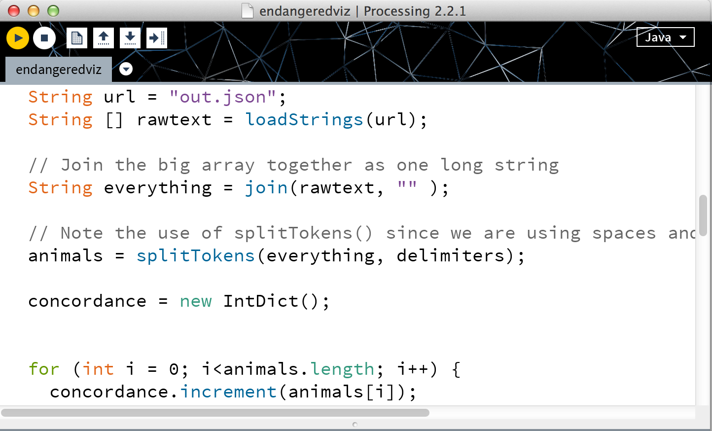
My idea was to create a data graphic using the Enigma.io's curation of the Federal government's tracking of endangered species in national parks and other areas. 

https://api.enigma.io/v2/data/a061071e73862a6e21d60d37a31dca60/us.gov.doi.fws.endangered-species?conjunction=and

I had issues with uploading my JSON data.  I tried using an NYTimes example which seemed similar to my goal, then I used a file which used a .txt file.  Neither were good templates. 

I need to work on my facility with strings, arrays, and classes further, as well as API requests. 


Fabrication Is Difficult to Do Well, or, A Trash Can Lamp.

I wanted to make a beautiful cylinder of sanded, polished wood, shorter than it was wide, into a battery powered lamp, turning our first fabrication project of creating a duct-taped circuit-style flashlight on its head and instead create something of quality, with heft. Grace of form.  A spare Noguchi-inspired shade. Underneath concentric rings of delicate pink, amber, blue gels. 

...So...didn't turn out like that.  I looked for turning wood for too long without succeeding in buying anything.  Also turns out I needed to know how to lathe and I don't. Yet.

I decided to prototype the form. 

I used a clear acrylic pipe-coupler-type cylinder.  It didn't occur to me to have them cut it there. I spent a lot of time on, and needed help, using a hacksaw and handscrew clamps to do it myself - it was brittle.  Rotary sanding the ends was interesting.  In trying to drill a hole to accommodate the switch I cracked the acrylic tube.  

In switching to a tube from a solid cylinder I realized I needed a good way to hold the circuitry in place. I used a mesh and the rim of an aluminum sieve.  The only aspect of my iteration I favored was the hand-sanding of the acrylic to give it a beach-washed glass look. I also kind of liked the concept I came up with of using netting to cradle the innards.  

If I were to attempt another iteration of this lamp I would start with a foam block and rough it out or I would settle for an imperfect but nicely rounded blob of wood before tackling the lathe.

It was a humbling experience.  Technique, experience, know-how, planning are important. Throwing lots of time and money at something at the last minute is no replacement. 


Physical Computing Final Project Brainstorm

A few ideas: 

1) A capacitive net (or wall) which blankets a person and via LEDs communicates changes in body energy.  I'm interested in the idea of qi and other bioelectromagnetic fields produced by organic tissues.  Could be a way to trigger lighting an occupied portion of a room or hallway like a reading lamp or a candle.  Maybe incorporating some kind of EEG sensor or theremin-like ambient sound element. Pros: seems like magic. Cons: possibly too ambitious and large scale.


2) Stereotypical Cube: A skin-tone and gender-guessing cube.  Muffled/diffused light and sound comes in and hits microphone and simple camera and compares against societal averages.  Output accuracy is questionable due to extraneous variables.  Need more research.  The concept would be centered around playing with stereotypical generalizations and making the user expose his/herself to vulnerability of being judged by a cube, a piece of "tech." 


3) An experiential blackout booth (glass?) supplied with several hidden sensors of different types which give the user an information about information collected about them while they where inside.   How they moved. What they said. Where their smart device was located on their body. This still-vague idea is aimed at raising awareness about surveillance.  

4) Working on a GPS & true north haptic navigation system project with Sam Sadtler from another section. Prototyping and adding haptic feedback sensors and interface for bike rider.

5) Mind Map: combined with ICM final this is a dynamic quandrant-continuum map designed to connect ITP people with similar interests, projects, skills, experience together.  This was originally conceived as an ICM and or Networked Media final as well as a utilitarian gift to our class.  I am wondering about mapping a physical space to share input. 

6) Sound bed - I'd like to explore making bedding with imbedded transducers so that people can be surrounded by bass as they sleep.  Could combine with brainstorm idea 1 - the capacitive net or wall. 

7) Halflife Hour Glass. The idea is to explore individual and human experience of time-passage.  A timepiece which tells the user using exponentially incremented luminance and tone-shift outputs from the time-piece when half of the remaining set time has passed, and then another iteration at half of that time and so on, until the final second is so minutely divided that the tone and luminance pulse/change becomes imperceptible and is perceived instead as a continuous state.  Exit condition is allowed at this point by manual interference from user.  Interaction comes from a) the user's inability to stop the countdown  b) the user's ability to mix and match combinations of increasing or decreasing luminance with ascending or descending frequency or c) a layered audio playback of recorded ambient noise begins at the first halftime (e.g. 30 minute marker) and then is layered under the next halftime recording so that in the end there is white noise or room harmonics.  Recommended to me by Arlene Ducao, Alvin Lucier's interative sound work I AM SITTING IN A ROOM is a strong reference point for this last interactive element.  A big difference is that the user can decide what to layer into the recording and move the timepiece from place to place if they wish - changing the resulting harmonics.  


More background research is needed on all. 

INTERACTIVE OCTOPUS :: Midterm Project Final Documentation

We set out to create an animated mini-animal avatar in Processing.  The concept was to encourage the user to experience a degree of transference to another type of being.  Initially we were considering a quadruped - like a polar bear.  But contemplating our hands we switched to an octopus because the look and feel of our fingers undulating in air was ripe for this kind of transformation. 

Doing a little background research; our project seems similar in its fundamental concept to to Karolina Sobecka's work with animal facial expressions.  

Initially considering using the lerp() function in Processing we stumbled upon Keith Peter's elegant segmented arm.  We spent a lot of time working to understand the sketch's trigonometry and structure so that we could manipulate it to suit our needs for our animation. 

We created a wearable controller using a kitchen glove, gaffer's tape, two flex sensors and an Adafruit Flora microprocessor. 

We tested a few iterations of our Interactive Octopus and it's physical interaction. 

We tested a few iterations of our Interactive Octopus and it's physical interaction. 

Here is a rough of our Flora circuit schematic. Originally we tweaked our sensor mapping with 5V power but since we were forced to use 3.3V we had to adjust our values - especially since we were dealing with sin/cos/atan values in our oscillating sketch objects. 

Here is our Interactive Octopus in action. 

Here is our Arduino code. 

Here is our Processing code as modified from Keith Peters. 

import processing.serial.*;
Serial myPort;

//DECLARE
Arm[] arrayArm=new Arm[8];
Arm myArm;

int numSegments = 50;

float[] x = new float[numSegments];
float[] y = new float[numSegments];
float[] angle = new float[numSegments];

float segLength = 12;
float targetX, targetY;

float xpos;
float ypos;
float xa;
float ya;

float armpos;
float armA;


void setup() {

  println(Serial.list());
  String portName = Serial.list()[0];
  myPort = new Serial(this, "/dev/tty.usbmodem1411", 9600);
  myPort.bufferUntil('\n');

  //noCursor(); 
  size(1440, 900);

  //INITIALIZE
  myArm = new Arm();

  for (int t=0; t<arrayArm.length; t++) {
    arrayArm[t]=new Arm();
  }
}

void draw() {
  background(0, 180, 195);

  fill(255, 120, 90);


  //ellipse(width*3/5, height*2/5, 220 + 10*sin(millis()/100), 220 + 10*cos(millis()/100));


  for (int t=0; t<arrayArm.length; t++) {
    pushMatrix();
    translate(width*4/6, height*2/5);
    ellipse(width-width, height-height, 100 + 10*sin(millis()/100), 100 + 10*cos(millis()/100));


    rotate (PI*t/13);


    arrayArm[t].display();
    for (int i=0; i<x.length; i++) {
      arrayArm[t].segment(x[i], y[i], angle[i], (i+1)*2);
    }
    popMatrix();
  }


  myArm.reachSegment(0, xpos, ypos);


  for (int i=1; i<numSegments; i++) {
    myArm.reachSegment(i, targetX, targetY);
  }
  for (int i=x.length-1; i>=1; i--) {
    myArm.positionSegment(i, i-1);
  }
}


void serialEvent(Serial myPort) {
  String myString = myPort.readStringUntil('\n');
  if (myString != null) {

    myString = trim(myString);
    int sensors[] = int(split(myString, ','));
    
    println();

    if (sensors.length >1 ) {
     
      
      xpos = map(sensors[0], 200, 988, PI/9, PI);
      ypos = map(sensors[1], 190, 467, 293, 971 );
      //armA = map(sensors[0], 115, 142, 0, height);


      }
    
    for (int sensorNum = 0; sensorNum < sensors.length; sensorNum++) {
      print("Sensor " + sensorNum + ": " + sensors[sensorNum] + "\t");
    }


    }
  }

class Arm {
  
//int sensorVal;
//int getSensorVal(){ return this.sensorVal; }
//int setSensorVal(int sensorVal){ 
//this.sensorVal = sensorVal; }
//
//for (int i = 0; i < mySensors.length; i++){
//         myArmArray[i].setSensorVal(mySensors[i]);
//}


  //CONSTRUCTOR
  Arm() {
 
  }
  
  //FUNCTIONS
  
  void pulseBody(){ 
    fill(255, 120, 90);
    
    //need to add accelerometer sensor values to body pulsing
   
 
  }
   
      void display(){
        
        strokeWeight(20.0);
        stroke(255, 120, 90);
        
       //set (x,y) to zero to perform transform and then rotate 
      x[x.length-1] = width-width;   // Set base x-coordinate
      y[x.length-1] = height-height;  // Set base y-coordinate
     
      
 // x[x.length-1] = width/3;   // Set base x-coordinate
 // y[x.length-1] = height/2;  // Set base y-coordinate
    
  }
  
  void positionSegment(int a, int b) {
  x[b] = x[a] + cos(angle[a]) * segLength+xpos/2.0;
  y[b] = y[a] + sin(angle[a]) * segLength - xpos/4.0;
}

void reachSegment(int i, float xin, float yin) {
  float dx = xin - x[i];
  float dy = yin - y[i];
  angle[i] = atan2(dy, dx);  
  targetX = xin - cos(angle[i]) * segLength;
  targetY = yin - sin(angle[i]) * segLength;
}

void segment(float x, float y, float a, float sw) {
  strokeWeight(sw);
  pushMatrix();
  translate(x, y);
  rotate(a);
  line(0, 0, segLength, 0);
  popMatrix();
}
  
}


Physical Computing Midterm Documentation A.1

//Arm Class Tab


class Arm {
  
  //CONSTRUCTOR
  Arm() {
 
  }
  
  //FUNCTIONS
  
  //how to rotate/translate/push/pop the arms?? 
  
    //void rotateArm(float r){
    //  rotate(r);
      
    //} 
      void display(){
      
  x[x.length-1] = width/3;   // Set base x-coordinate
  y[x.length-1] = height/2;  // Set base y-coordinate
    
  }
  
  void positionSegment(int a, int b) {
  x[b] = x[a] + cos(angle[a]) * segLength;
  y[b] = y[a] + sin(angle[a]) * segLength;
}

void reachSegment(int i, float xin, float yin) {
  float dx = xin - x[i];
  float dy = yin - y[i];
  angle[i] = atan2(dy, dx);  
  targetX = xin - cos(angle[i]) * segLength;
  targetY = yin - sin(angle[i]) * segLength;
}

void segment(float x, float y, float a, float sw) {
  strokeWeight(sw);
  pushMatrix();
  translate(x, y);
  //rotate(a);
  line(0, 0, segLength, 0);
  popMatrix();
}
  
}


//Object/functions


//DECLARE
Arm myArm1;
Arm myArm2;

int numSegments = 50;

float[] x = new float[numSegments];
float[] y = new float[numSegments];
float[] angle = new float[numSegments];

float segLength = 4;
float targetX, targetY;


void setup() {

  noCursor(); 
  size(640, 360);
  strokeWeight(20.0);
  stroke(255, 120, 90);
 
  
  //INITIALIZE
  myArm1 = new Arm();
  myArm2 = new Arm();

}

void draw() {
  background(0, 180, 195);
  ellipse(215, 180, 20, 20);
  
  
   pushMatrix();
   rotate (0);
  myArm1.display();
 popMatrix();
 //WHY ARE THESE NOT ROTATING SEPARATELY ACCORDING TO ROTATE FUNCTION radian VALUES????
  pushMatrix();
   rotate (PI/2);
  myArm2.display();
 popMatrix();


   //pushMatrix();
   //myArm2.rotateArm(PI/8);
   //popMatrix();
   
  // pushMatrix();

  //myArm1.rotateArm(0);
  
  //popMatrix();


  myArm1.reachSegment(0, mouseX, mouseY);
  for (int i=1; i<numSegments; i++) {
    myArm1.reachSegment(i, targetX, targetY);
  }
  for (int i=x.length-1; i>=1; i--) {
    myArm1.positionSegment(i, i-1);
  } 
  for (int i=0; i<x.length; i++) {
    myArm1.segment(x[i], y[i], angle[i], (i+1)*2);
  }
  
    myArm2.reachSegment(0, mouseX, mouseY);
  for (int i=1; i<numSegments; i++) {
    myArm2.reachSegment(i, targetX, targetY);
  }
  for (int i=x.length-1; i>=1; i--) {
    myArm2.positionSegment(i, i-1);
  } 
  for (int i=0; i<x.length; i++) {
    myArm2.segment(x[i], y[i], angle[i], (i+1)*2);
  }
}


Working it out Good Will Hunting style. The green and red lines and notation follow the variables to understand the code structure and the trigonomic algorithms which control the variable relationships inside each function.&nbsp;

Working it out Good Will Hunting style. The green and red lines and notation follow the variables to understand the code structure and the trigonomic algorithms which control the variable relationships inside each function. 

"Octopus arm" composed of 50 segments whose individual size and position are dictated by the cursor's x sin and y cosine. This is what creates an organinc wave effect where each segment is sequentially displaced along an oscillation graph in relatio…

"Octopus arm" composed of 50 segments whose individual size and position are dictated by the cursor's x sin and y cosine. This is what creates an organinc wave effect where each segment is sequentially displaced along an oscillation graph in relation to the mouseX and mouseY original positions. 


Creative Tone & Servo Lab/ Analog Inputs, Digital Outputs

For my creative expansion on the servo OR tone labs I chose to make a combination of the two.  I used an analog photoresistor input to map the analog tone output for the piezometer standing in for a speaker.  

Next I wired the servo to digital pin 3 and mapped the servo angle output to a potentiometer's analog input into analog pin 5.  

Then I added a fan-blade or light blocking "flag" to the servo motor's blade/axis and positioned it over the photoresistor/piezometer to modulate that circuit without needing to go through the Arduino.   

servotonelab